Bradford White BWCH Operations Instructions
Browse online or download Operations Instructions for Water heaters & boilers Bradford White BWCH. Bradford White BWCH Operating instructions User Manual
- Page / 64
- Table of contents
- BOOKMARKS
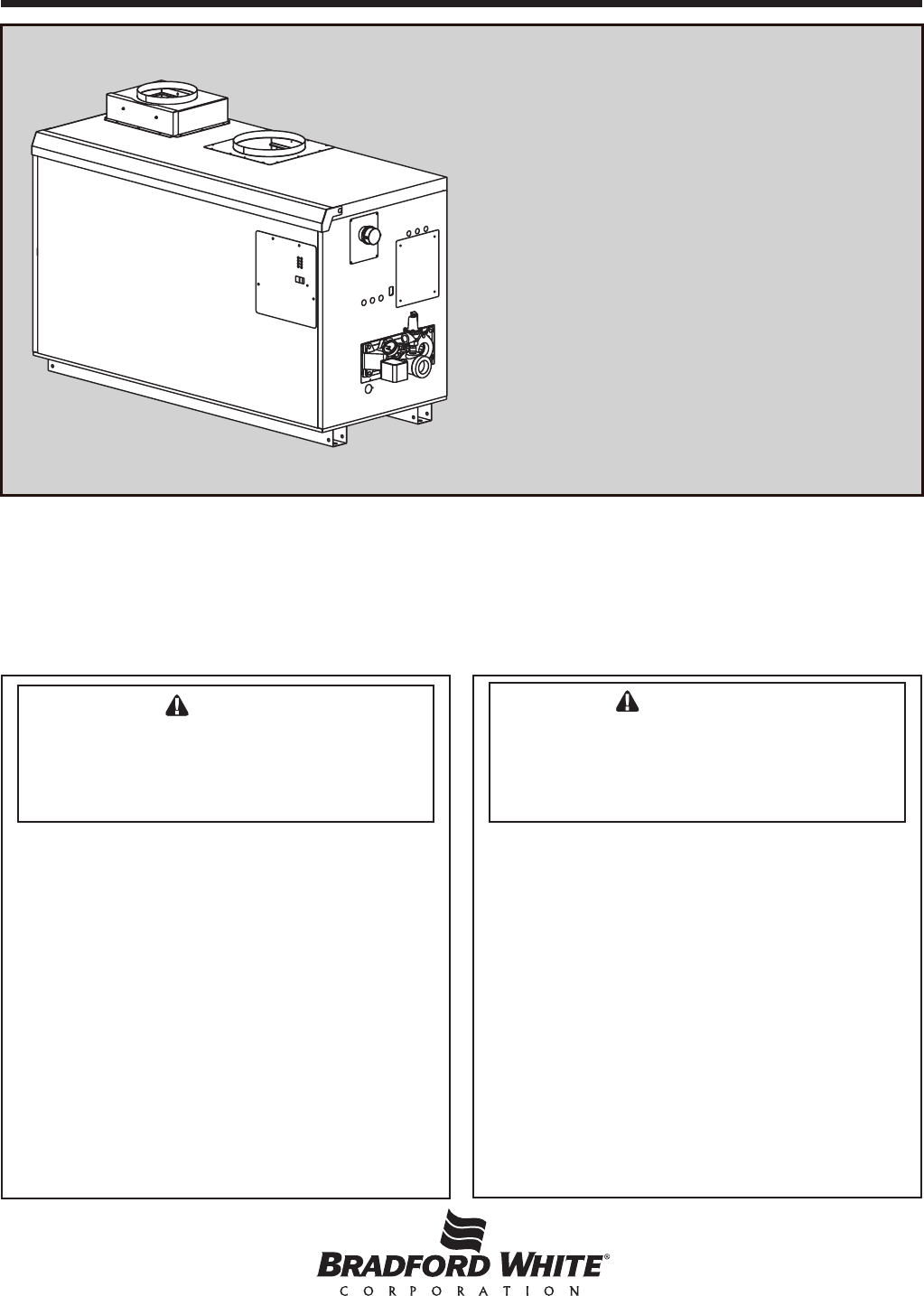
- Copper Brute II 1
- TABLE OF CONTENTS 2
- SECTION 1 4
- General Information 4
- 1.3 Warranty 5
- 1.4 Dimensions 5
- 1.5 Locating the Appliance 5
- SECTION 2 8
- Venting and Combustion Air 8
- 2.2 Venting 9
- BRADFORD WHITE CORP 10
- Terminals 11
- SECTION 3 13
- Gas Supply and Piping 13
- SECTION 4A 14
- Water Connections — 14
- Copper Brute II Boiler 14
- COPPER BRUTE II (500 - 2000) 15
- SECTION 4B 20
- Copper Brute II Water Heater 20
- 1 THROUGH 7.5 21
- SECTION 5 24
- Electrical Connections 24
- Figure 22. Field Wiring 33
- SECTION 6 36
- Operating Instructions 36
- Caution 41
- 6.4 Advanced Topics 42
- SECTION 7 48
- Maintenance 48
- SECTION 8 51
- Trouble Shooting 51
- Controls 52
- SECTION 9 54
- Replacement Parts 54
- Internal Components 55
- Electrical Components 61
- Ambler, PA 19002 64
- Tech. Service (800) 334-3393 64
Summary of Contents
Installation and Operation Instructions Document 1270H2214401FInstallation and OperationInstructions for WARNINGIf the information in this manual is
Page 10 BRADFORD WHITE CORP. U.S. Installations (see note 1) Canadian Installations (see note 2)A = Clearance above grade, veranda, porch, 12
Page 11COPPER BRUTE II (500 - 2000)appliances. If assistance is required in determining how a blocked vent safety system should be connected to a Brad
Page 12 BRADFORD WHITE CORP.2.3.3 Vertical Vent TerminalWhen the unit is vented through the roof, the vent must extend at least 3 feet (0.9m) above
Page 13COPPER BRUTE II (500 - 2000)DISTANCE FROM GAS METEROR LAST STAGE REGULATORSIZE ANDGAS TYPE 0-100' 0-31m 100-200' 31-61m 200-300&ap
Page 14 BRADFORD WHITE CORP. 20°F 25°F 30°F 35°F SIZE ow H/L ow H/L ow H/L ow H/L gpm feet gpm feet gpm feet gpm feet 500 43
Page 15COPPER BRUTE II (500 - 2000)PRIMARY/SECONDARY MANDITORY FOR ALLVARIABLE FLOW SYSTEMSINSTALL AIR VENTS AT HIGH POINTS IN SYSTEMPIPING&SIZING
Page 16 BRADFORD WHITE CORP.PRIMARY/SECONDARY MANDITORY FOR ALLVARIABLE FLOW SYSTEMSINSTALL AIR VENTS AT HIGH POINTS IN SYSTEMPIPING & SIZING OF
Page 17COPPER BRUTE II (500 - 2000)Figure 6. Hydronic Piping — One Boiler, Multi-Temperature System.PRIMARY/SECONDARY MANDITORY FOR ALLVARIABLE FLOW S
Page 18 BRADFORD WHITE CORP.LEGENDCHECK VALVETHERMOMETERTEMPERATURESENSORGLOBE VALVEEXPANSION TANKWITH AIR SCOOP ANDAUTO AIR VENT3-WAY VALVEVALVECAUT
Page 19COPPER BRUTE II (500 - 2000)LEGENDCHECK VALVETHERMOMETERTEMPERATURESENSORGLOBE VALVEEXPANSION TANKWITH AIR SCOOP ANDAUTO AIR VENT3-WAY VALVEVAL
Page 2 BRADFORD WHITE CORP.SECTION 1. General Information1.1 Introduction ... 41.2 Model Identi
Page 20 BRADFORD WHITE CORP.SECTION 4B.Water Connections — Copper Brute II Water Heater4B.1 Water System Piping — Water HeaterHot water piping shou
Page 21COPPER BRUTE II (500 - 2000)Figure 9. Water Heater Piping — One Heater, One Tank.NOTES:6. CAUTION: PUMP SIZING MUST BE BASED UPON WATER HARDNES
Page 22 BRADFORD WHITE CORP.Figure 10. Water Heater Piping — Multiple Heaters, One Tank.Figure 11. Water Heater Piping — One Heater, Multiple Tanks.
Page 23COPPER BRUTE II (500 - 2000) GPM FT TEMP RISE °F LPM M TEMPRISE°C SIZE S N H S N H S N H S N H S N H S N H 500 45
Page 24 BRADFORD WHITE CORP. SINGLE CIRCUIT CONNECTIONS PUMP HEATER ONLY W/O PUMP WITH PUMP 500 15 20 15 750 15 20 151000 20 25 151250 2
Page 25COPPER BRUTE II (500 - 2000)Figure 14. Field Wiring Panel Figure 15. External Control Connection Wiring.with the Copper Brute II is installed i
Page 26 BRADFORD WHITE CORP.additional components.5.3 External Staging Control Wiring WARNINGImproper eld wiring may result in re or explosion whi
Page 27COPPER BRUTE II (500 - 2000)Figure 16. Copper Brute II 500 - 750 Ladder Diagram.
Page 28 BRADFORD WHITE CORP.Figure 17. Copper Brute II 1000 Ladder Diagram.
Page 29COPPER BRUTE II (500 - 2000)Figure 18. Copper Brute II 1250 - 2000 Ladder Diagram.
Page 3COPPER BRUTE II (500 - 2000)SECTION 6. Operating Instructions6.1 Sequence of Operation ... 366.2 Filling the Bo
Page 30 BRADFORD WHITE CORP.Figure 19. Copper Brute II 500 - 1000 Wiring Schematic.
Page 31COPPER BRUTE II (500 - 2000)Figure 20. Copper Brute II 1250 - 1500 Wiring Schematic.
Page 32 BRADFORD WHITE CORP.Figure 21. Copper Brute II 1750 - 2000 Wiring Schematic.
Page 33COPPER BRUTE II (500 - 2000)Figure 22. Field Wiring.Note: Positions of eld wiring terminals may vary, but terminal designations are as indicat
Page 34 BRADFORD WHITE CORP.Figure 23. Field Wiring for Modes 1 - 5.Note: Positions of eld wiring terminals may vary, but terminal designations are
Page 35COPPER BRUTE II (500 - 2000)Figure 24. Field Wiring for Mode 6.1C1NO2C2NO3C3NO4C4NO4C3C4NO3NO2C1C2NO1NO4stage boiler using4 control outputs4sta
Page 36 BRADFORD WHITE CORP.SECTION 6.Operating Instructions6.1 Sequence of OperationA call for heat can be initiated either automatically (auto mod
Page 37COPPER BRUTE II (500 - 2000)radiation units and high points in the system piping, as described in Step 4.12. Close make-up water valve and che
Page 38 BRADFORD WHITE CORP. APPLICATION MODE SYSTEM SETTING SENSORS USED • Parallel piping (non- primary/secondary) hydronic system 1 •
Page 39COPPER BRUTE II (500 - 2000)Figure 27. Temperature Control Target Temperature Graph.delay setting of 5 minutes. See Section 6.4.6 for more
Page 4 BRADFORD WHITE CORP.SECTION 1.General InformationUSING THIS MANUAL – Because the Copper Brute II Boilers and Copper Brute II Water Heaters are
Page 40 BRADFORD WHITE CORP.Programming. Mode 2 is used in primary-secondary piping hydronic systems without outdoor reset. Mode 5 adds outdoor reset
Page 41COPPER BRUTE II (500 - 2000) CautionIf the tank temperature control is set too high, a potential for hot water scalding may exist.Mode 2: Prim
Page 42 BRADFORD WHITE CORP.Figure 28. Temperature Control Interstage Differential.6.4 Advanced Topics For most installations, Section 6.3 provide
Page 43COPPER BRUTE II (500 - 2000)Figure 29. Temperature Control Min & Max.minimum amount of time before turning on the next stage. After the min
Page 44 BRADFORD WHITE CORP.Figure 30. Temperature Control Outdoor Start Graph.the time selected (between 0 and 10 minutes). When OFF is selected, th
Page 45COPPER BRUTE II (500 - 2000)Figure 31. Typical Gas Train Conguration.Figure 32. Typical Control Panel.the typical coldest temperature of the y
Page 46 BRADFORD WHITE CORP.The control then operates the boiler stages to maintain the programmed boiler target temperature. The reset override oper
Page 47COPPER BRUTE II (500 - 2000) (b) The ame will go out and blower will continue to run for the post purge cycle. One additional attempt to lig
Page 48 BRADFORD WHITE CORP.SECTION 7.Maintenance7.1 System Maintenance1. Lubricate the system water-circulating pump, if required, per the instruc
Page 49COPPER BRUTE II (500 - 2000)and boilers ordered with low temperature controls. To replace the switch, shut off the 120-volt power to the applia
Page 5COPPER BRUTE II (500 - 2000)Model Character Designation1-3 Model Series Designation B W C = Bradfrod White, Copper Brute II4 Usage H = Hydr
Page 50 BRADFORD WHITE CORP.6. Allow the heat exchanger to drain. Remove the front cover(s) by removing the rubber access strip(s) and the retaining
Page 51COPPER BRUTE II (500 - 2000)a load distribution problem. See Section 6.3 regarding controller setup. Contact your Bradford White representative
Page 52 BRADFORD WHITE CORP.8.6 Troubleshooting the Temperature ControlSee Table 12.8.7 Troubleshooting Copper Brute II ControlsThe Copper Brute II
Page 53COPPER BRUTE II (500 - 2000)Table 12. Troubleshooting Error Codes.
Page 54 BRADFORD WHITE CORP.Item Description Size Size Size Size Size Size Size 500 750 1000 1250 1500 1750 2000 Sheet Metal Components
Page 55COPPER BRUTE II (500 - 2000) Internal Components See Figures 35 and 3417 Base Assembly 5C1020 7C1020 10C1020 12C1020 15C1020 17C1020 2
Page 56 BRADFORD WHITE CORP. (1) (1) (2) (2)36 Tile, Rear T2015700 (1)37 Tile, Rear, Left Side T2017500 T2016600 T2016600 T20
Page 57COPPER BRUTE II (500 - 2000)Item Description Size Size Size Size Size Size Size 500 750 1000 1250 1500 1750 2000 Relief Valve, BWC
Page 58 BRADFORD WHITE CORP.71 High Limit, Manual Reset, BWCH RE0015900 RE0015900 RE0015900 RE0015900 RE0015900 RE0015900 RE0015900 High Lim
Page 59COPPER BRUTE II (500 - 2000) Burner Manifold Assy, 4 Burners, Left, LP 10C6520 10C6500 10C6520 10C6520 (2) (2) (2) (4)78
Page 6 BRADFORD WHITE CORP.Figure 1. Dimensional Data.SHIPPING WEIGHTSIZE lbs. kg500 425 193750 505 2291000 615 2791250 675 3061500 760 34517
Page 60 BRADFORD WHITE CORP.Figure 33. Sheet Metal Components.12345678910111213141616B16C16D16ABASE SHOWNFOR REFERENCENOTE: Model 2000 shownfor refer
Page 61COPPER BRUTE II (500 - 2000)Figure 34. Internal Components.SeeElectrical Componentsfor detail.
Page 62 BRADFORD WHITE CORP.Figure 35. Heat Exchanger Components.See pump chart below for pump numbers.Copper Brute II Hydronic SIZE PUMP P/N 500
Page 63COPPER BRUTE II (500 - 2000)Figure 36. Electrical Components.
H2214401FBradfordWhiteCorp.reservestherighttochangespecications,components,features,ortodiscontinueproductswithoutnotice.Ambler, PA 1
Page 7COPPER BRUTE II (500 - 2000)1.6 Locating Pump-Mounted Water Heater with Respect to Storage Tank(s)For best results, a pump-mounted Copper Brute
Page 8 BRADFORD WHITE CORP.Figure 2. Combustion Air and Vent Through Roof. EACH OPENING* SIZE SQUARE INCHES SQUARE CM 500 125 807 750 188 1
Page 9COPPER BRUTE II (500 - 2000)length allowed is 50 feet (15.2m). Three elbows have been calculated into the 50-foot (15.2m) linear run. Subtract 1
Related products and manuals for Water heaters & boilers Bradford White BWCH
 (20 pages)
 (12 pages)
© 2020, manymanuals.com. All rights reserved. | 0.621 s |
 Manymanuals.com
 Manymanuals.de
 Manymanuals.fr
 Manymanuals.it
 Manymanuals.pl
 Manymanuals.cz
 Manymanuals.es
 Manymanuals-pt.com
Comments to this Manuals